DEC 30, 2024
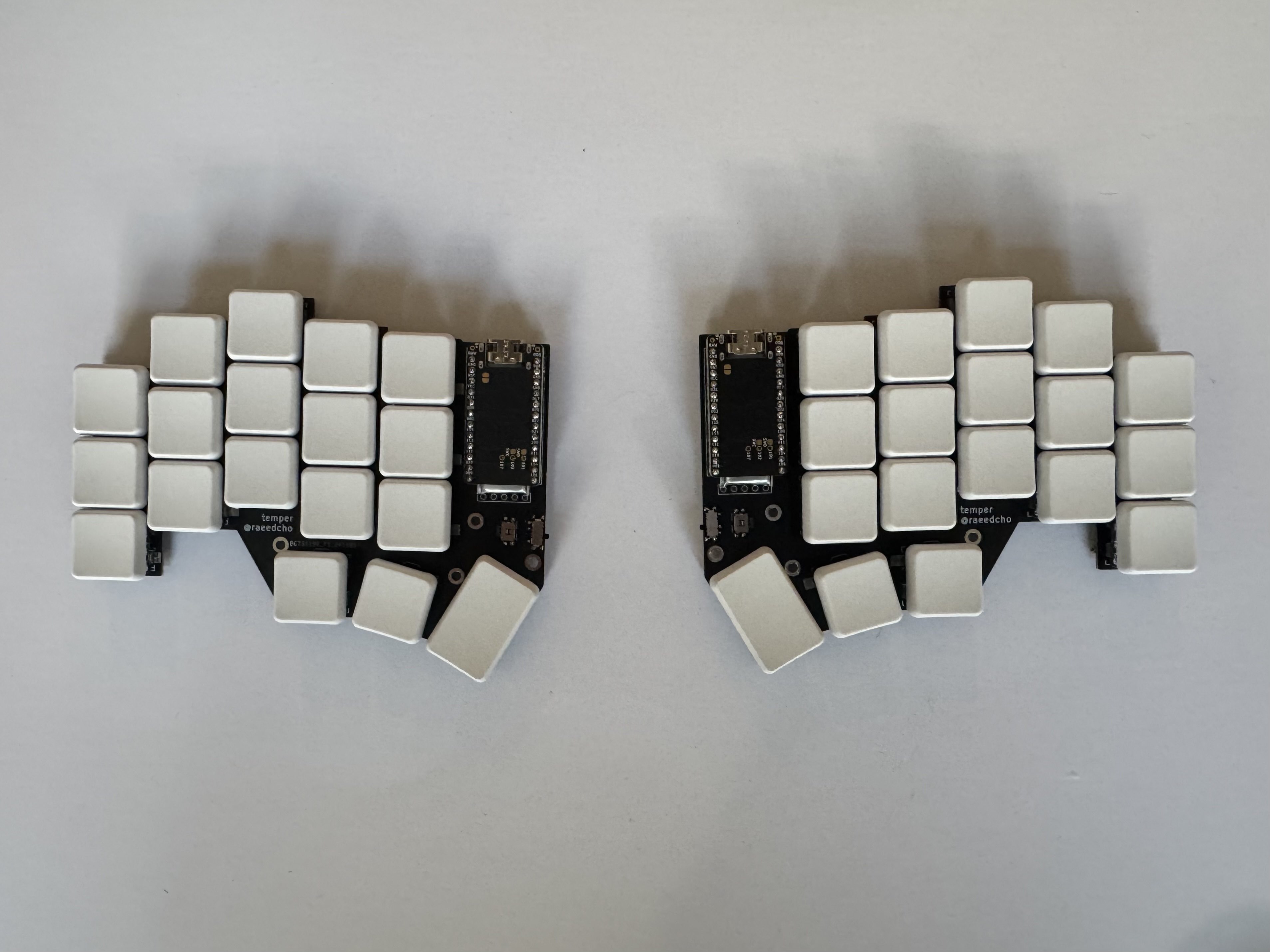
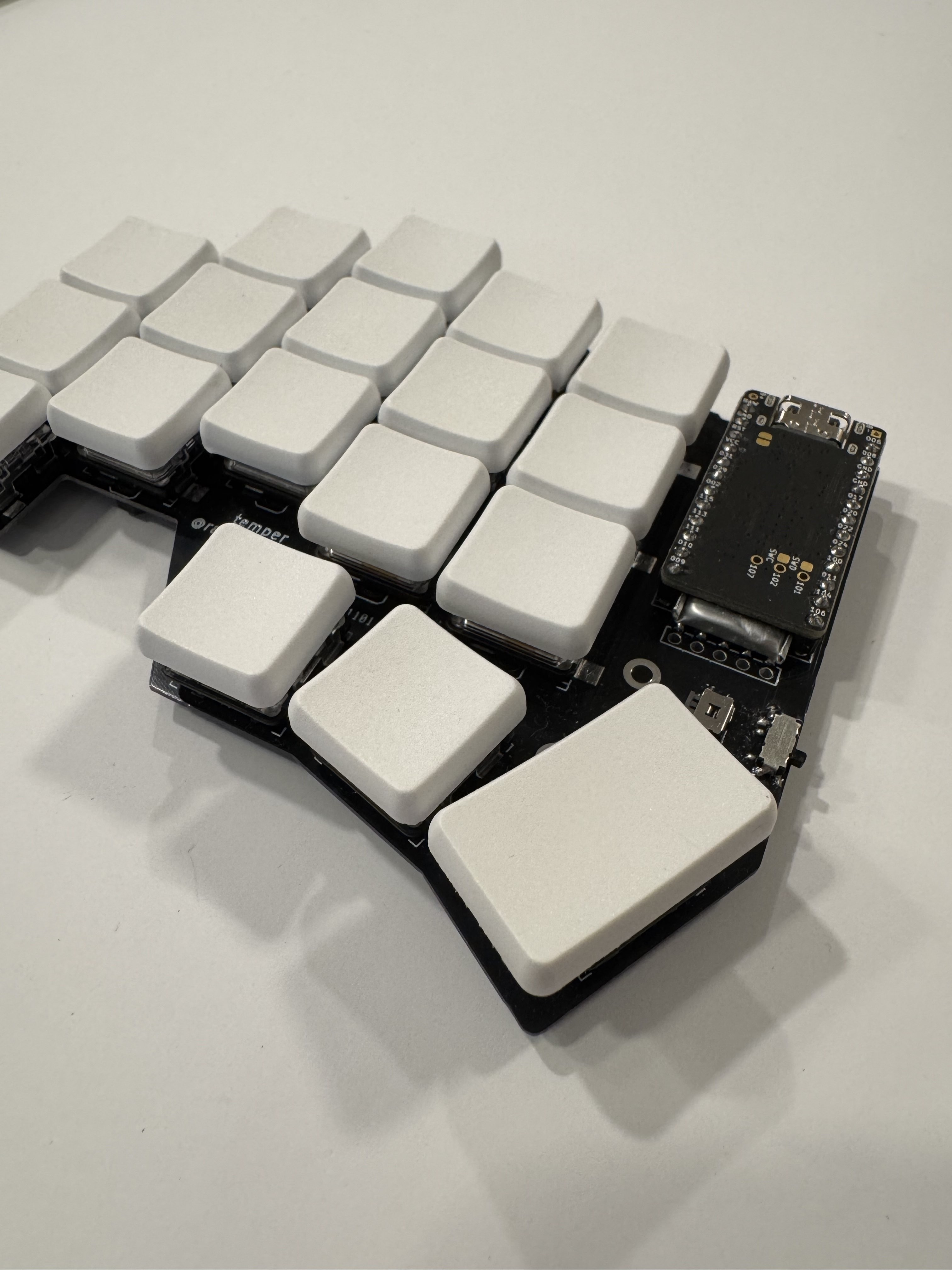
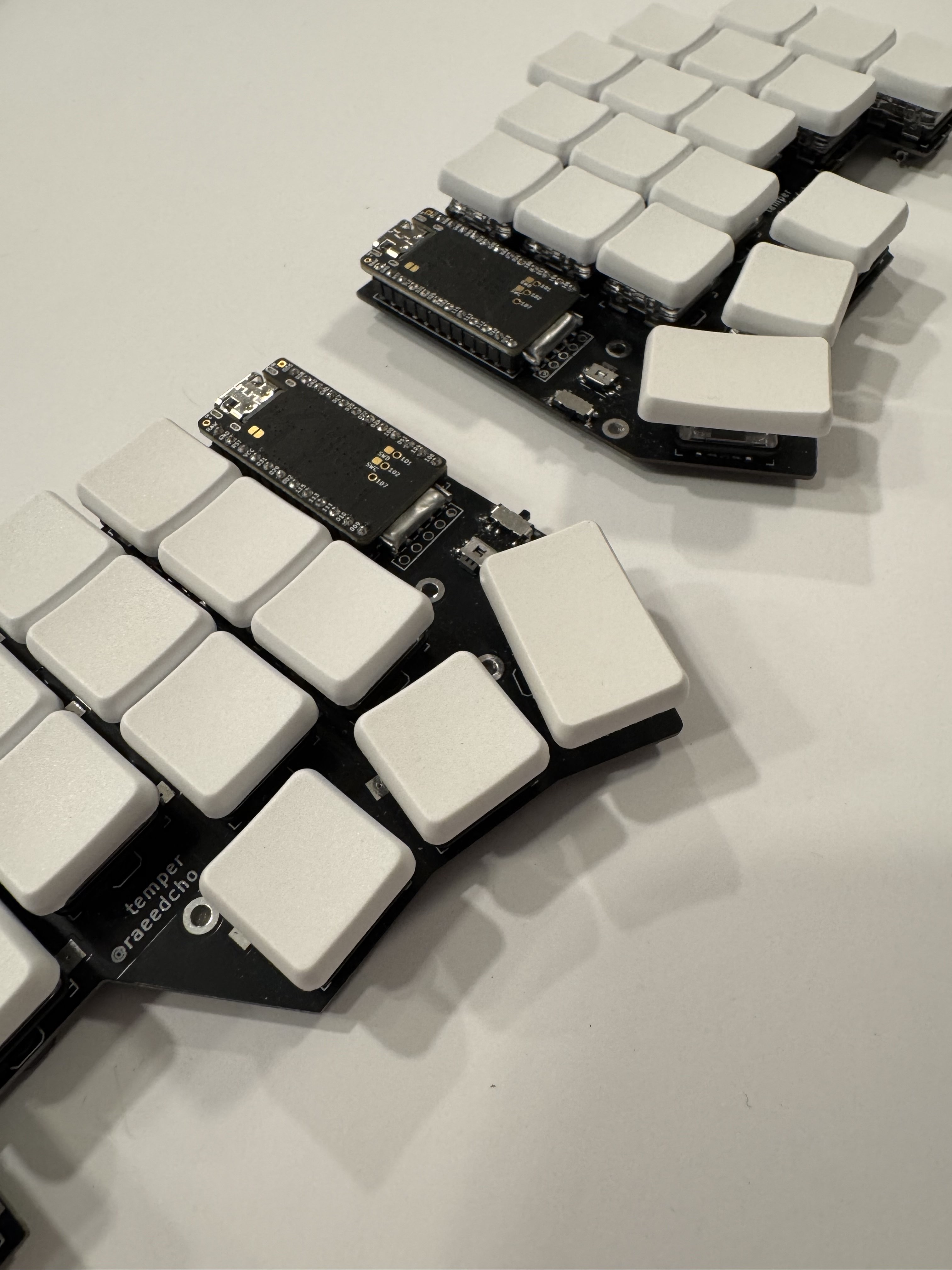
building the temper, a low profile ergo mech keyboard
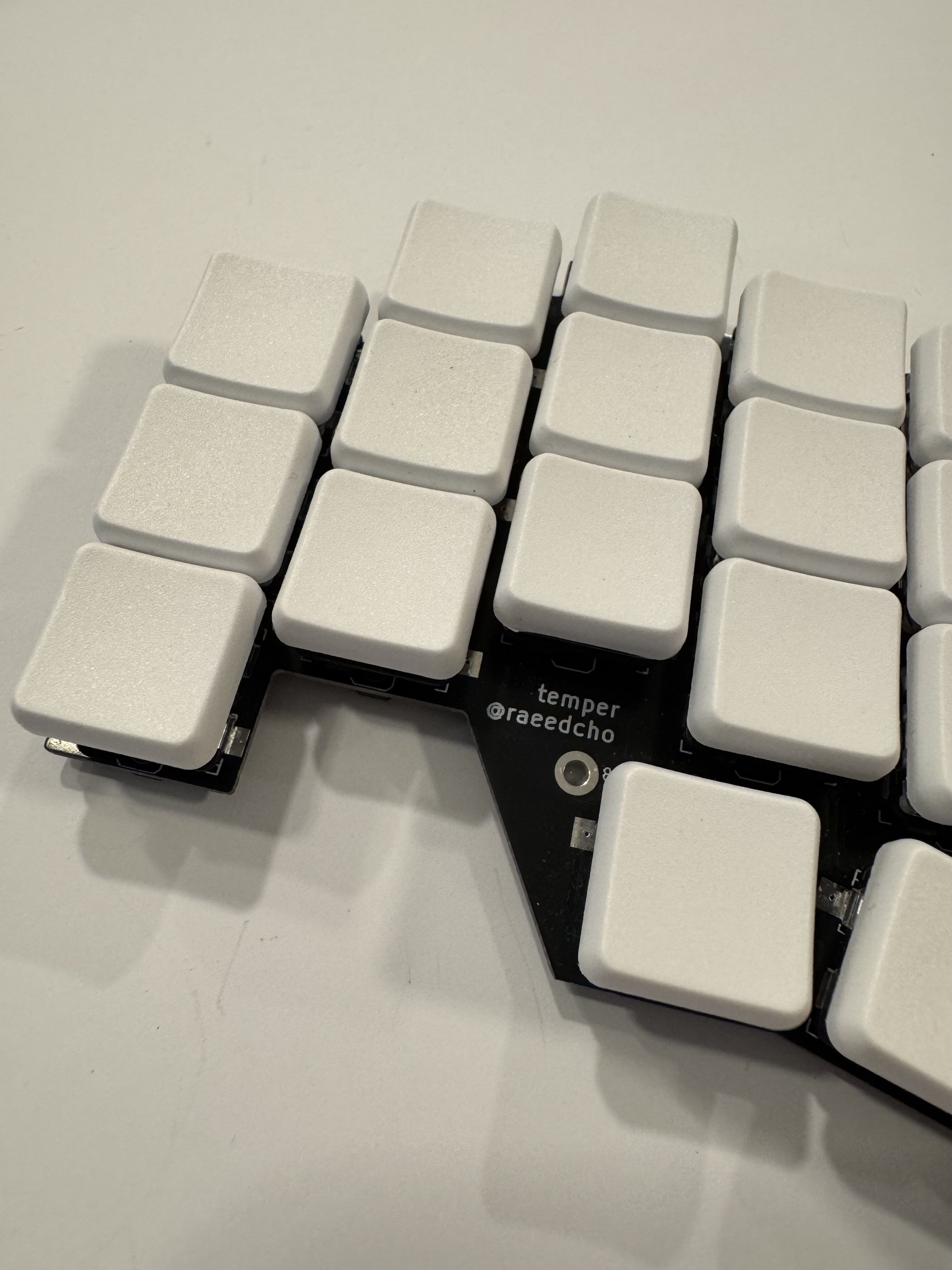
or, a first foray into open-source hardwareIf you know anything about me, it will not surprise you to learn that I have been tangentially interested in mechanical keyboards for a while now. [1] I finally ended up (kind of unintentionally) building one—here she is!
Anyway, here’s how it happened.
“look, how hard could it possibly be?”
Sometime during the summer, I committed to getting a new mechanical keyboard.[2] I wanted it to be
- low profile
- ergonomic
- tactile
- split, and
- preferably small
A quick internet search revealed that there are a whole host of options for split ergonomic keyboards. But all the keyboards I was looking at were not exactly products in stores? They were more…uh, GitHub repositories? That had “gerber files” and sometimes a “bill of materials” and maybe a “build guide”? Huh. And then life got a little busier, so I filed it away in the back of my head. I wasn’t in any rush; I’d just find out how to buy one of these sometime later.
Fast forward to a couple weeks later, and I was constantly hearing from this sneaky voice in my head—a lot of “why don’t you just do it?” and “you’re an engineer, come on!” and some “look, how hard could it possibly be?”. For reference: at this point, I had tried soldering…erm…twice? Maybe three times? Honestly, I’m not sure where the unwarranted confidence came from.[3]
But surprising absolutely nobody, I gave in to temptation. I decided that I would build the temper, a 36-key wireless split ortholinear keyboard.[4]
buying parts and stuff
After deciding to go with the temper, I had to buy all the parts. Luckily, the bill of materials provided on the temper README is quite detailed. I followed it as exactly as I could, purchasing everything from four vendors: JLCPCB, Chosfox, DigiKey, and Typeractive. This went much smoother than expected—it turns out that it is indeed legal to just buy things.[5]
Again, not a surprise, but I am the kind of person that appreciates a good spreadsheet, so…behold! Here’s everything that I bought.
bill of materials
I should note that the table includes some extra diodes and switches[6] (~\$4), but I didn’t include the extra nice!nano and mill-max socket/pin set that I ended up buying (~$32). I also didn’t include shipping, taxes, or customs fees in the costs (too much work).
Anyway, after making my spreadsheet, I ordered all the parts and promptly started wiggling with excitement.
In a week or so, all the parts had arrived.
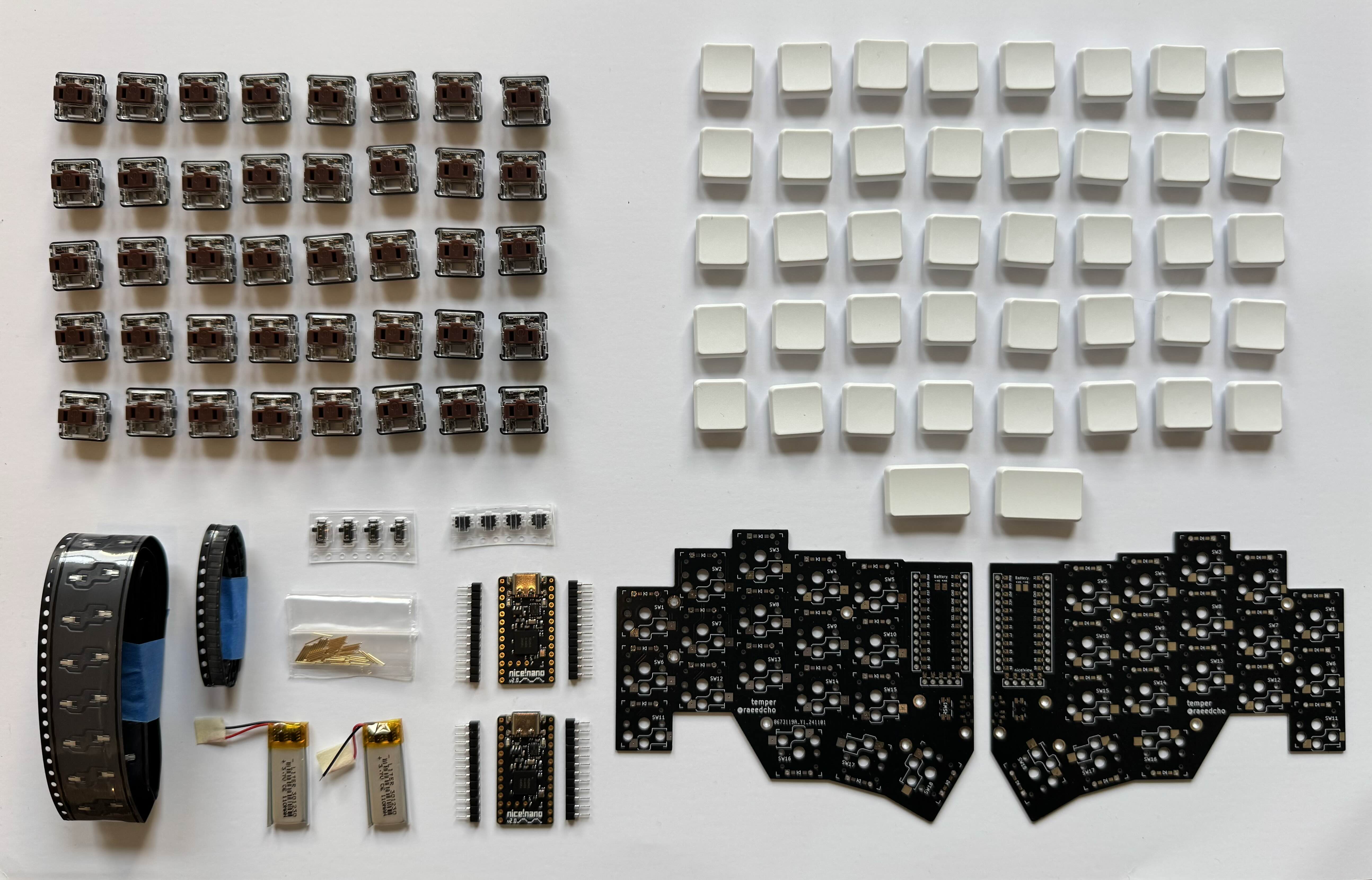
(I will not discuss in detail the amount of pure joy I experienced while laying everything out.)
putting it all together
Once I had all the parts, I just had to put it together. The plan went something like this:
- solder jumpers
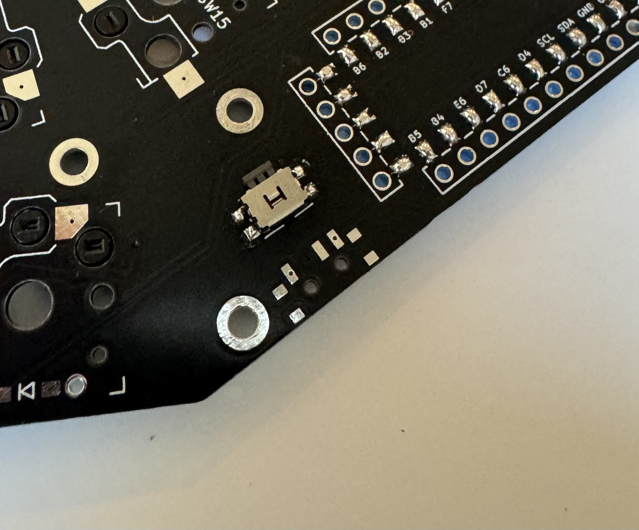
- solder diodes, hotswap sockets, and reset/power switches
- socket microcontroller
- solder battery
- put on switches, keycaps, and feet
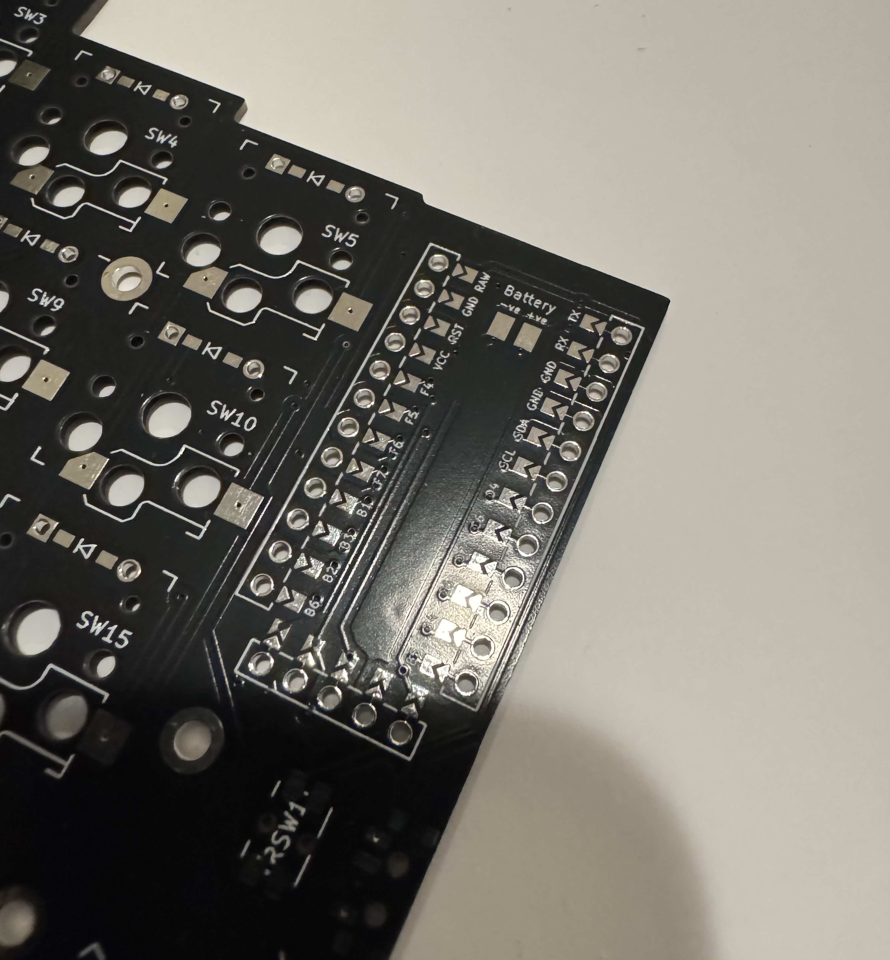
soldering the jumpers
Soldering the jumpers was pretty straightforward; I just followed the instructions on the temper README. I did do a practice run on one of the extra PCBs (minimum order at JLCPCB is 5, and I only needed 2), which was honestly quite helpful.
diodes, et. al.
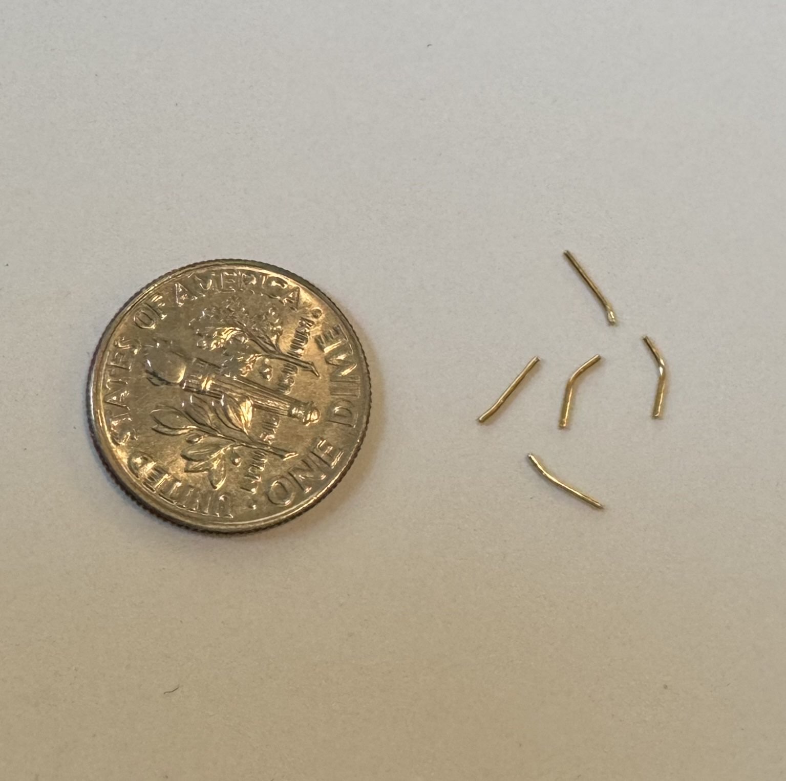
Successfully soldering the jumpers gave me quite a bit of confidence, which was immediately taken down a notch once I saw how small the diodes were.
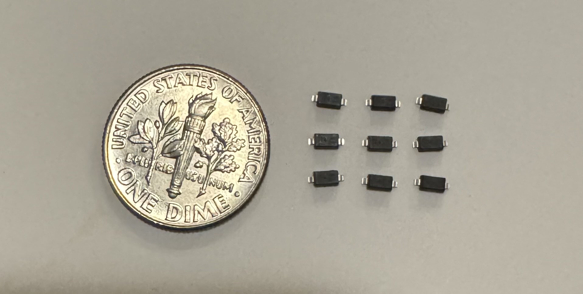
I was also a little scared because I knew from circuits classes (and burning countless LEDs) that the direction of a diode is very important. But I found this lovely guide that explained the general strategy for soldering on the diodes, as well as the direction that they should be placed. The main takeaway was that you want to start by putting a little solder on one pad, heat that pad and place the diode, and then handle the other side.
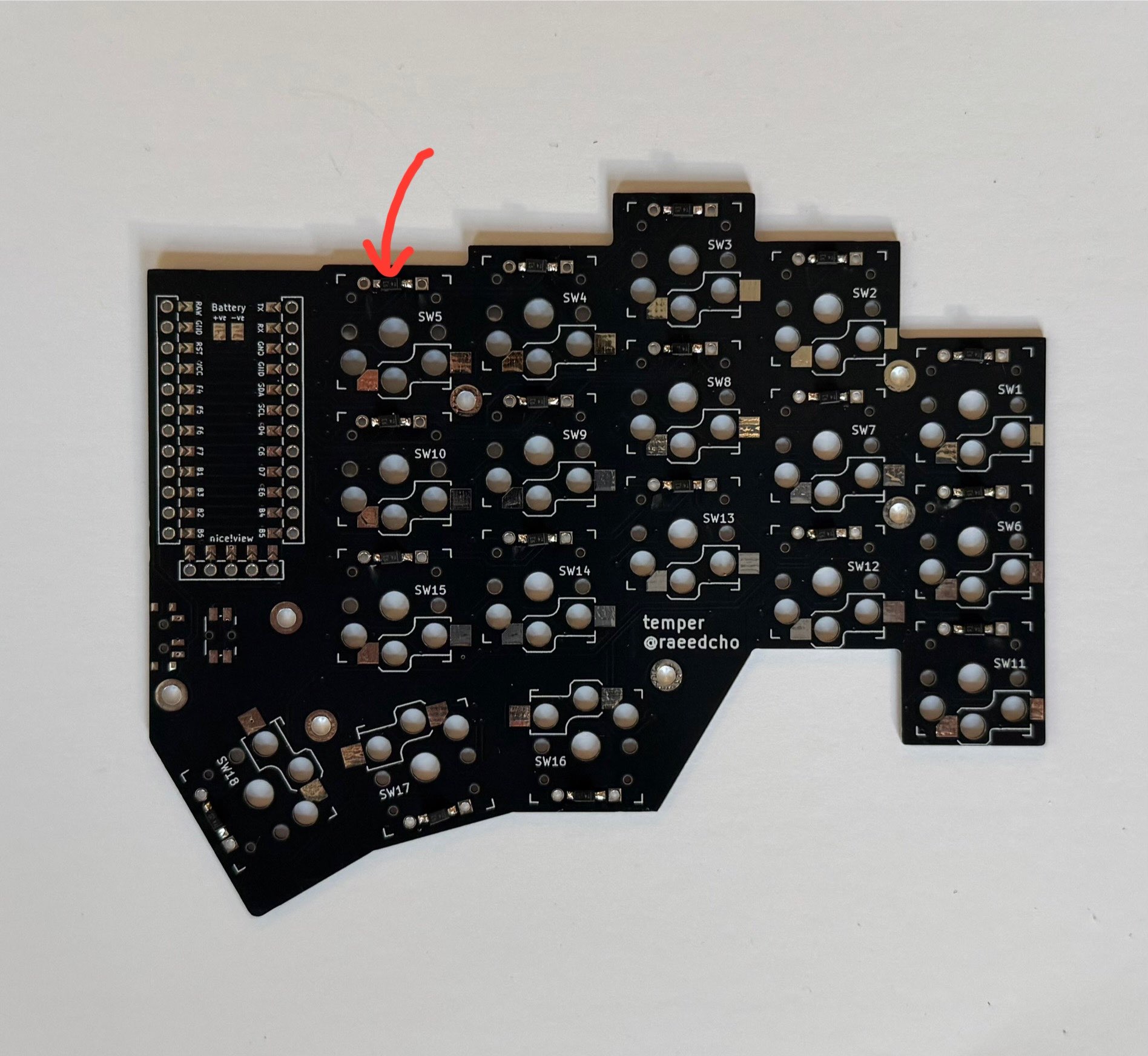
Next up were the hotswap sockets. They were a little confusing, but the PCB very conveniently had markings that made it impossible to do it wrong.
The one annoying thing was that there were now four pads instead of two, which made lining things up a little harder. But I was able to get them soldered on nicely, using the same strategy as before (start with a blob of solder on one of the pads).
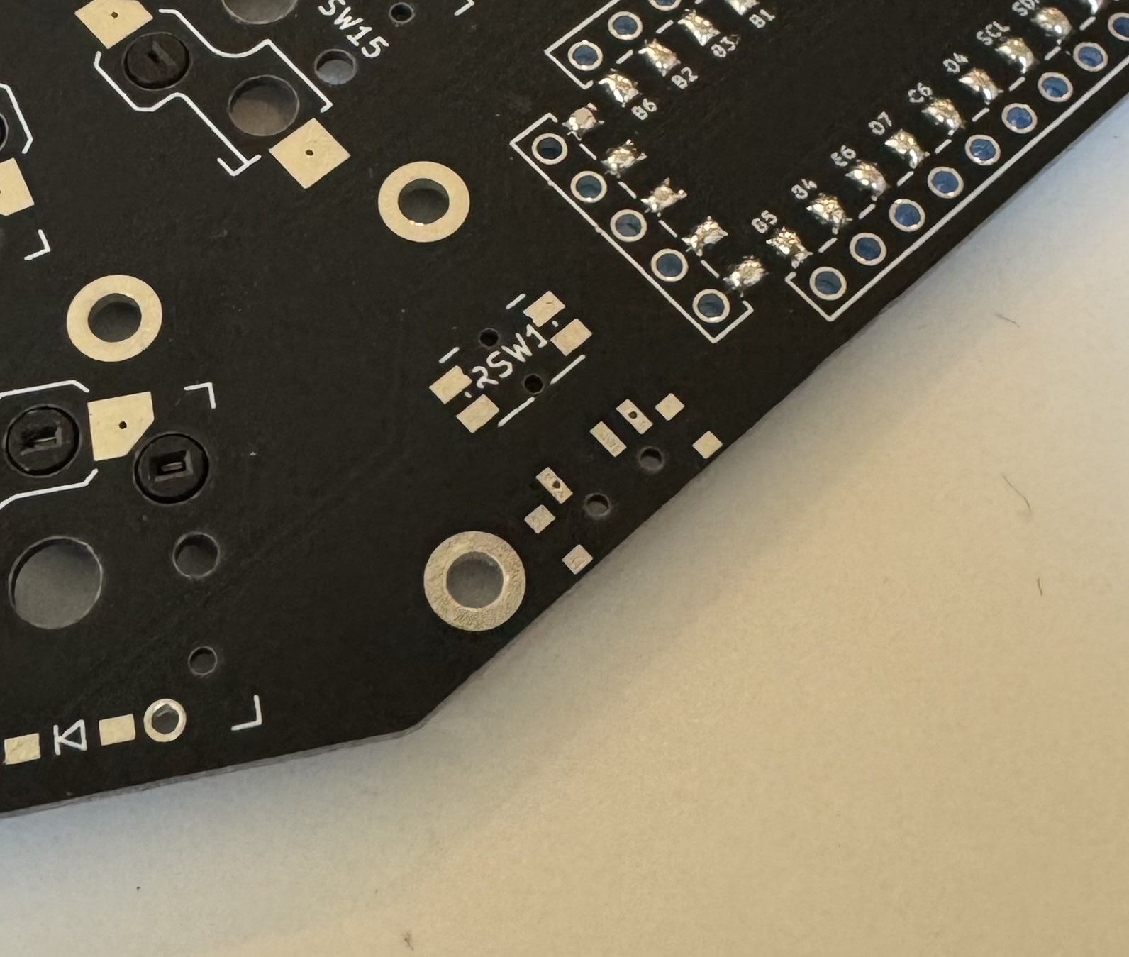
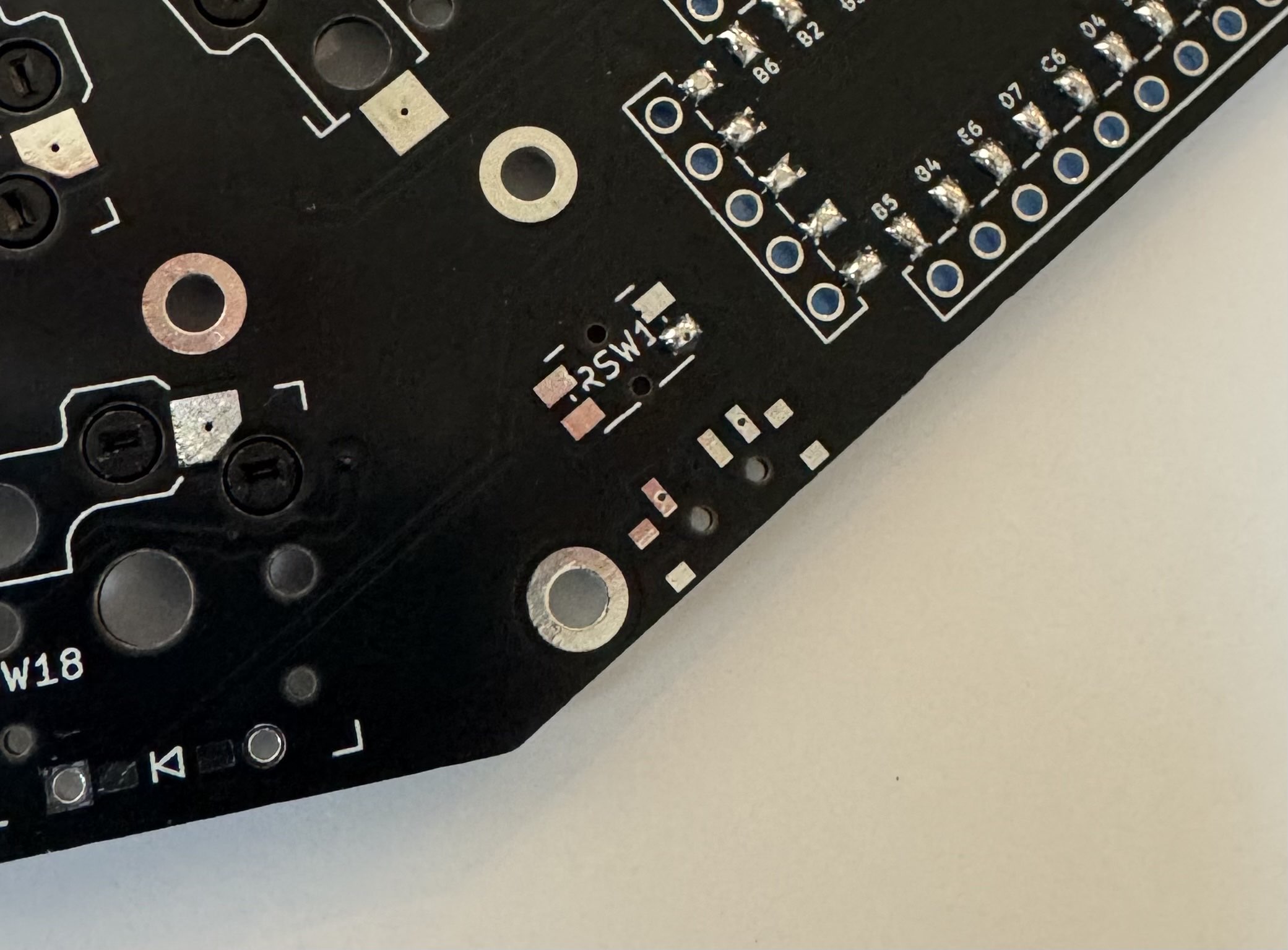
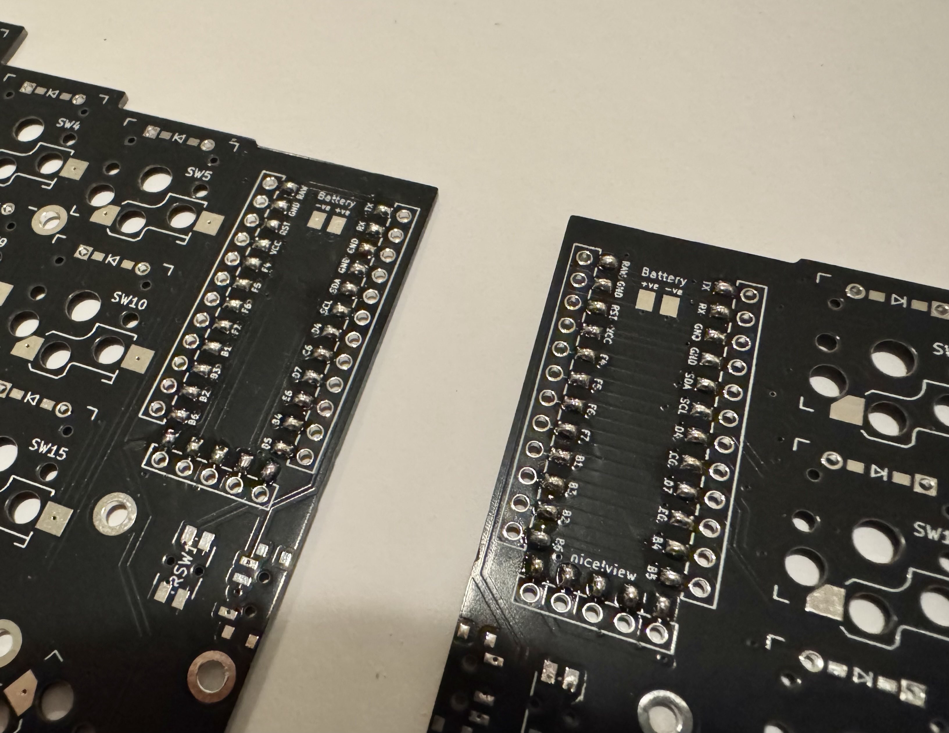
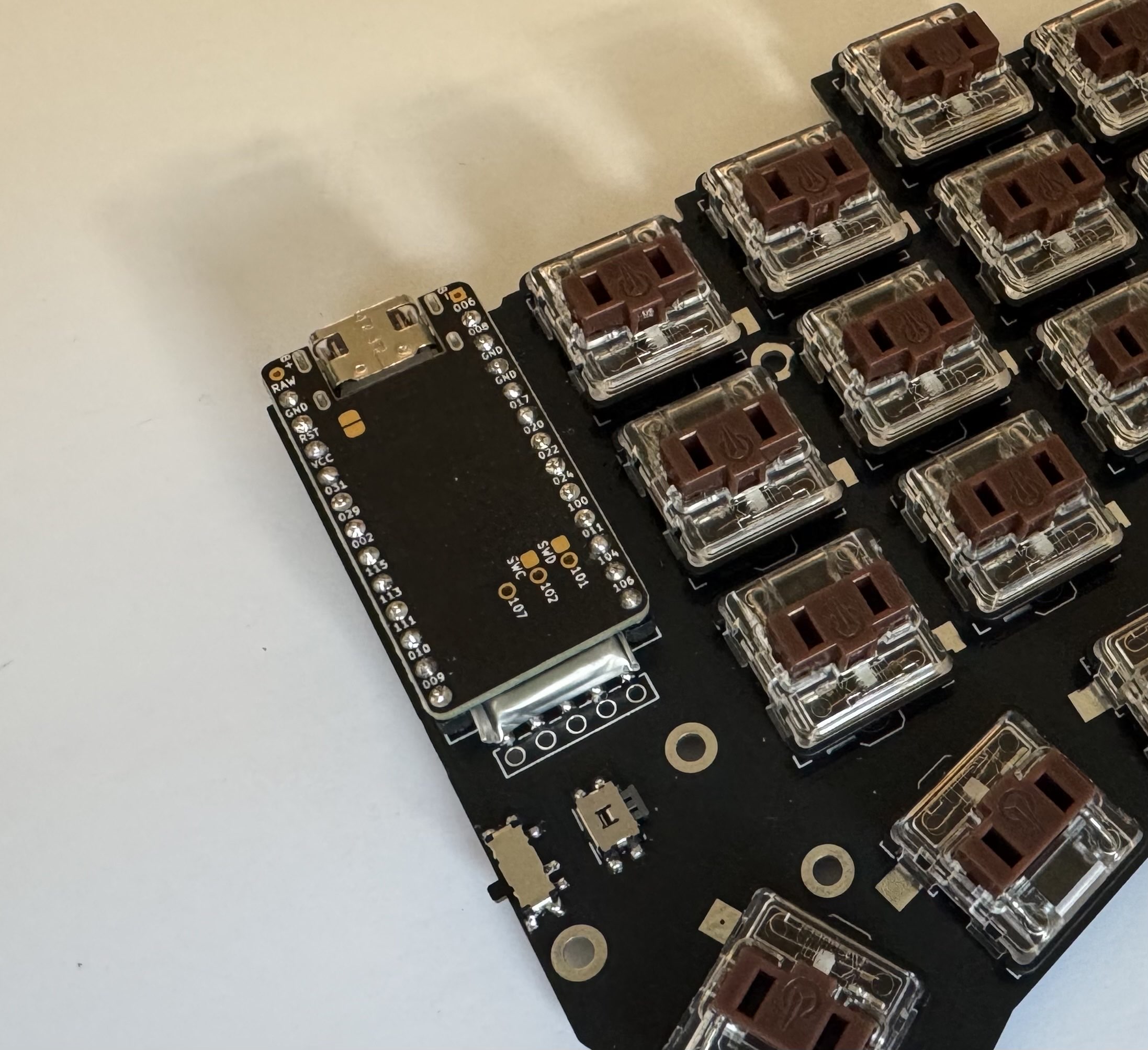
socketing microcontroller
Now past the halfway point, the next thing to do was to socket the nice!nanos. Basically, I needed to solder sockets to the PCB and pins to the nice!nanos so that I could plug and unplug them easily. This is technically optional—you could just solder the microcontroller directly to the PCB. But boy, was I glad that I did (foreshadowing alert!).
Anyway, there’s a guide linked in the README, which I followed.[7] The big idea is to solder while the pins, sockets, and nice!nano are in place (to make sure everything will fit), but to use a bit of painter’s tape to prevent solder from leaking through and sticking everything together.
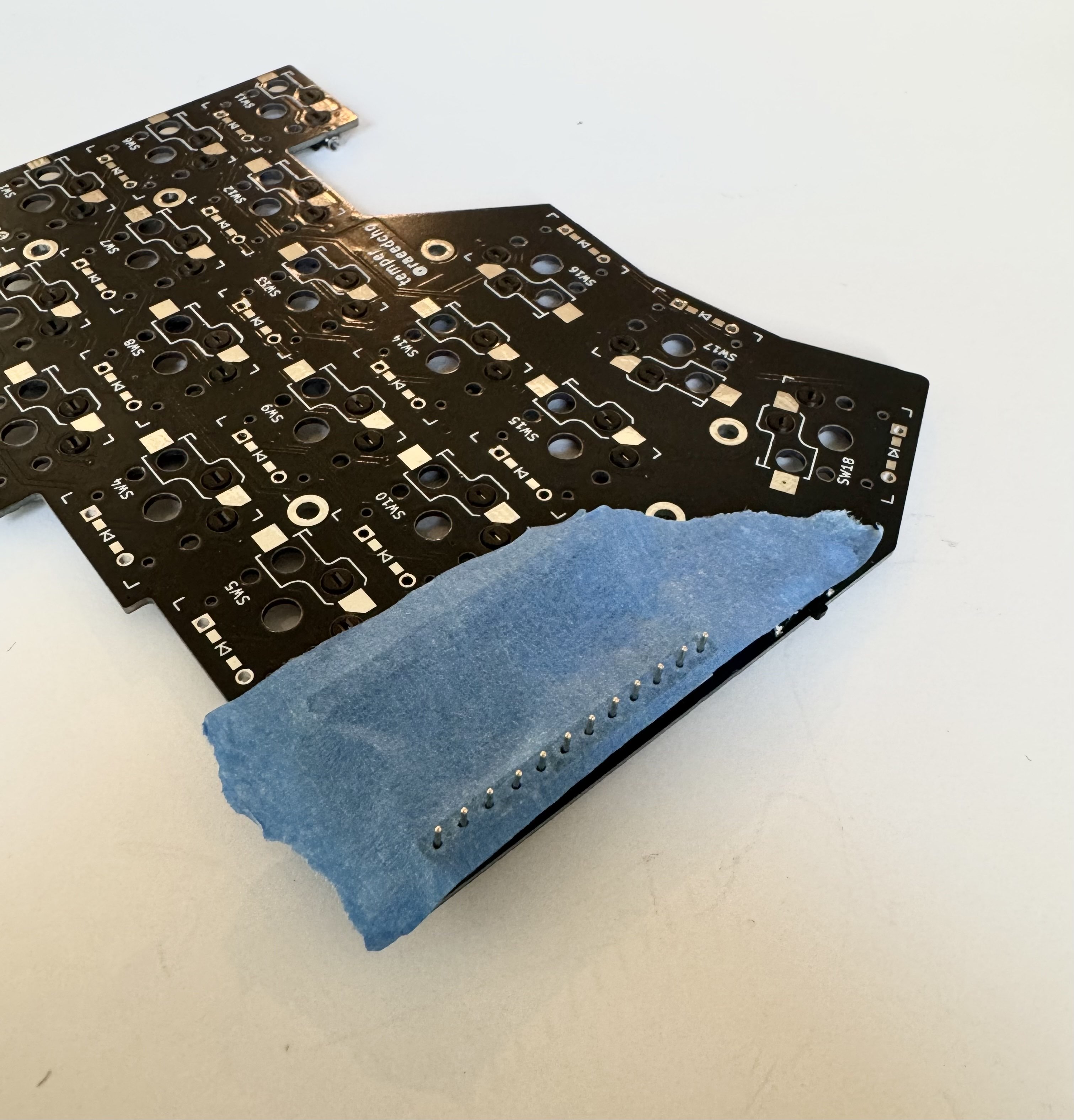
Sticking the pins through the tape was quite painful—they kept slipping through my tweezers, and I didn’t have any pliers. I found it worked best to take a flat object and gently press down on the pin, but it inevitably came with some casualties.
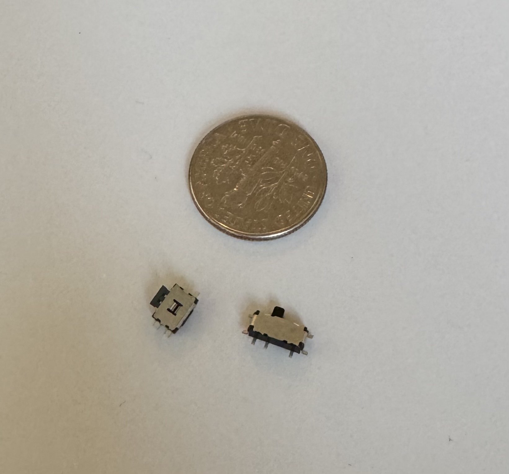
battery!
The last thing to solder was the battery, which was simple but nerve-wracking. I’m always afraid of blowing things up when working with batteries, so there was a lot of double-checking—red wire to +, black wire to -, make sure they don’t touch, etc. I wrapped up the ends in masking tape like the README recommended, and slotted the battery in between the microcontroller sockets.

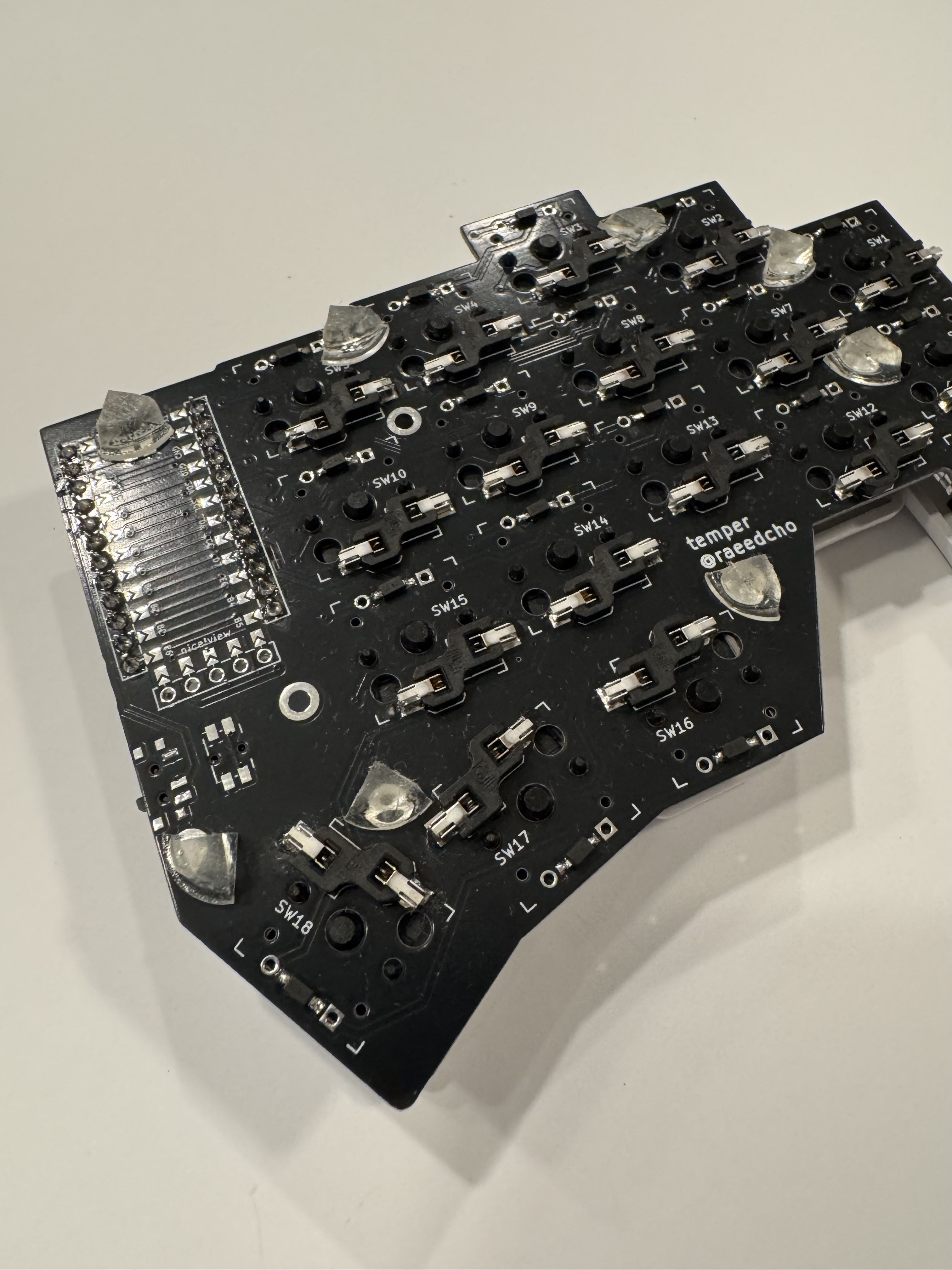
finishing touches and a little debugging
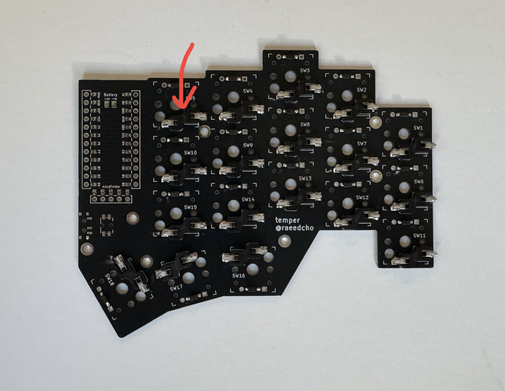
Once everything was soldered, I just needed to plug in the switches and the keycaps. I took a little care to make sure I wasn’t bending the switch pins, but other than that, simple and easy!
Once these were in, I tested each of the keys to make sure the connections were solid. A couple of them didn’t work, but the fix was easy—I just had to redo some obviously bad solder joints.
I also cut up some…I think they’re called cabinet bumper pads? to use as ad hoc keyboard feet. I found that this was surprisingly effective at preventing the keyboard from sliding around (though you want to place them so the keyboard doesn’t tilt over when hitting keys at the edges).
And then the assembly was all done!
on layouts and firmware
Once the physical form of the keyboard was complete, it was time to get its brains up and running. The temper README mentions that it was added to Mirokyu ZMK as an outboard, which I assumed meant that all my problems had already been solved. There was only one small issue, which was that I had no clue what it meant to be added to Mirokyu ZMK as an outboard.
So there were three things to figure out—what is Mirokyu, what is ZMK, and what does it mean to be added as an outboard?
Actually, I had come across Miryoku in the early stages of picking out the keyboard that I wanted. The thing that took me a bit to realize is that Mirokyu is a keyboard layout, just like QWERTY or Dvorak. In particular, Mirokyu is a layout for 36-key keyboards, designed for the tiny number of keys and optimized for ergonomics.
On the other hand, ZMK is firmware—it’s the software on your keyboard that talks to your computer. Putting that together, it should make sense that Mirokyu ZMK is the implementation of the Mirokyu layout for ZMK—it’s actual software that lets you use the Mirokyu layout on keyboards that use ZMK.
As such, Mirokyu ZMK needs to know something about the physical keyboard you want to build firmware for, and that’s where being “added as an outboard” comes in. It means the creator of the temper had already done the necessary configuration for you to use the Mirokyu layout on the temper.
In short, all my problems had already been solved.
Anyway, after figuring this all out, I built the firmware using GitHub Actions. There was a little bit of fiddling—I wanted to use QWERTY[8] and increase the Bluetooth transmission power,[9] which took me a second to figure out.[10]
But now it works like a charm!
final thoughts and opinions
The keyboard is great. I can feel the difference in ergonomics, especially when using keyboard shortcuts—no more crazy pinky chording! (I am definitely a home row mod afficionado.) It’s also been nice to have my hands further apart. I didn’t think it would matter that much, but occasionally swapping back to a regular keyboard makes me realize how scrunched my shoulders used to be.
There is still a little to get used to. For example, I don’t type quite as fast as I can on a regular keyboard. But it only took a week or two until I was typing fast enough, and I don’t think it’s that big of a deal at this point. I’d say the actual worst part is that I’m not fully accustomed to typing symbols (which makes setting LaTeX a pain in the ass).
Past the keyboard itself, this project gave me a new appreciation for open-source hardware. I really enjoyed Building A Thing, and the experience reminded me that I can change my physical reality, which was pretty cool. I’ll definitely do it again sometime! I got to make something is truly mine.
I am a programmer, gamer, and former engineering student with a history of repetitive strain issues, lol. ↩︎
I can neither confirm nor deny the whether r/MechanicalKeyboards had any impact on this decision. ↩︎
But I’m glad it was there. It probably helped that I didn’t know too much; had I known how tiny SMD diodes are, I might have given up before I even started. ↩︎
Some others I considered were the Ferris, Corne, Sofle, and chocofi. ↩︎
the wonders of capitalism! also, my lawyer would like me to mention that it is not legal to buy all things. just most things. the legal ones. ↩︎
They’re small, cheap, and easy to lose or damage. ↩︎
I used Mill-Max pins and sockets. ↩︎
For now…maybe I will change my mind. But that’s an adventure for another time. ↩︎
This fixed some connection issues I was having. ↩︎
Set
boardtonice_nano_v2,shieldtotemper_left,alphastoQWERTY, andkconfigtoCONFIG_BT_CTLR_TX_PWR_PLUS_8=y. Then build. Do it again fortemper_right. It seems obvious in hindsight that you need to build two different UF2 files, once for each half, but it wasn’t exactly clear at the time. ↩︎